After helping tens of thousands of people get started with the world of electronics and Arduino-based microcontroller projects with the Arduino Workshop book, it was time to help and guide people further into more complex ideas and concepts that can enable a greater variety of possibilities.
Those who have worked through “Arduino Workshop” or a lesser book and are curious to learn more about what can be done with an Arduino or compatible board,
Anyone with some experience in electronics and coding, who is happy to skip into more intermediate topics straight away.
People who need a reference book for the wide variety of hardware and software tools described in the book,
You. Yes, you. Learning is for a lifetime, and you’re reading this – so why not continue with the world of electronics and microcontrollers? Or give a copy to someone who enjoys learning more about technology?
Arduino for Arduinians is printed using a convenient lie-flat technology, so you can have the book open to your side and not worry about the pages flapping about and losing your position while working on your projects. All the required code is included in the book, however you can also download them along with a list of parts and supplier information from the book’s website.
Anyone with a modicum of Arduino knowledge can use this book, and if you’re coming from a different microcontroller platform – I genuinely believe you can get started with this book as well.
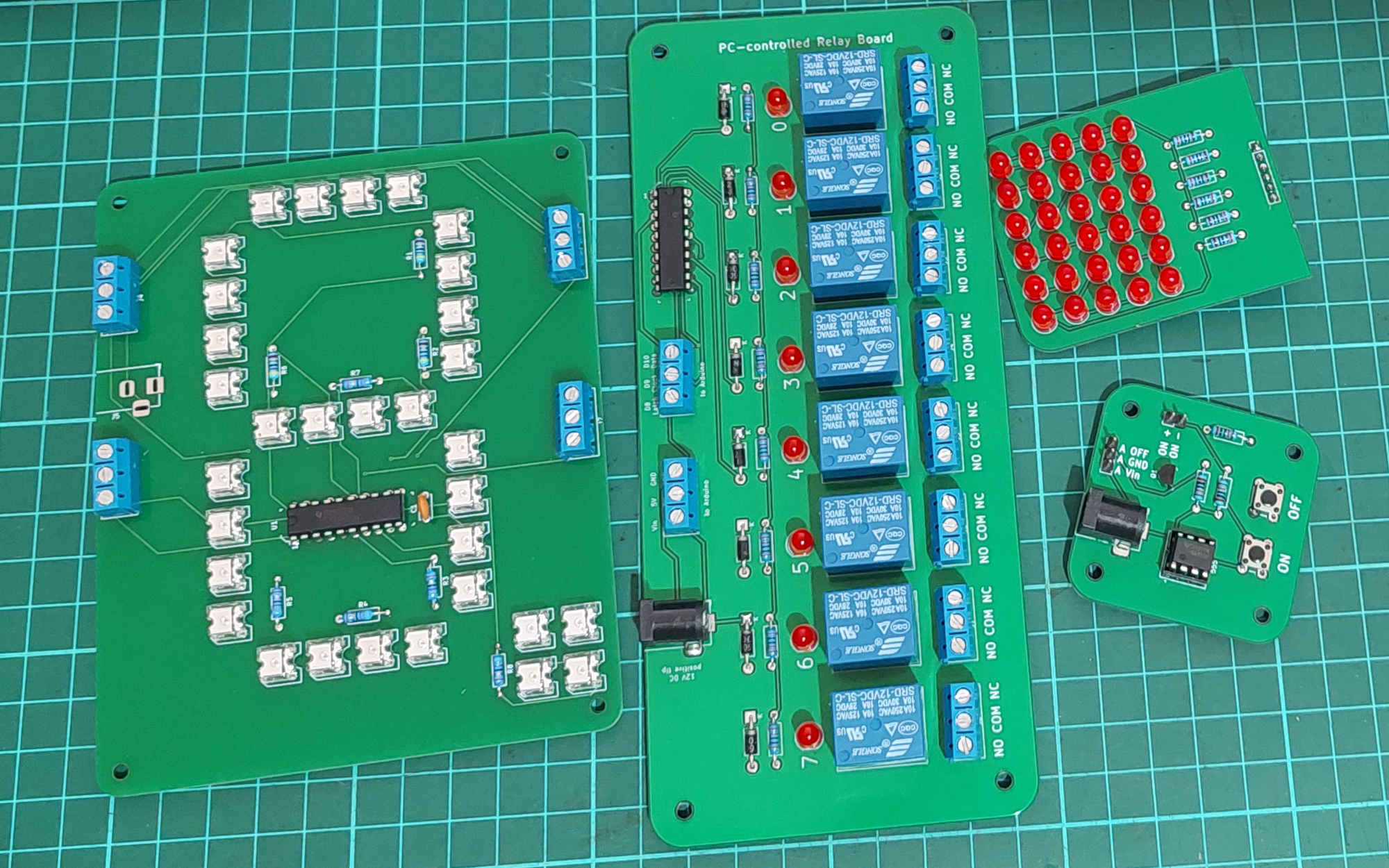
In some of the chapters, the use of external circuitry is required for ease of assembly, and in these cases you can download gerber files to have your own PCBs manufactured by one of the many low-cost providers. A sample of the project prototype PCBs are shown below:
And unlike some other books, each and every project has been built and tested so you can be confident of finding success very quickly.
The 8-bit Arduino platform is still, in my opinion, an inexpensive and most approachable way of learning about electronics and microcontrollers – and opens up a whole new world of creativity or even the pathway to a career in technology. A copy of Arduino for Arduinianswill help the accomplished Arduino beginner continue with their journey.
To learn more about Arduino for Arduinians, you can review the table of contents, download a sample chapter, Arduino sketches and parts list and order copies for yourself and others from the No Starch Press online store. Orders from No Starch Press also include a free electronic copy so you can get started immediately.
You can also purchase copies from amazon, kindle, or your preferred bookseller.
If you are reading via Kindle on a PC – don’t copy and past the code from the Kindle reader. Instead, download the files from the book website.
After many years working with and teaching others about the Arduino development platform, it became apparent that there needed to be a useful guide to get people started in the world of AVR microcontrollers – used in Arduino and other development environments. The great people at No Starch Press agreed and we are now proud to have published “AVR Workshop – A Hands-On Introduction with 60 Projects“.
AVR Workshop is written for several groups of people:
Those of you who have used an Arduino but now want to learn how to harness the underlying AVR microcontrollers without the layer of Arduino abstraction.
Anyone interested in electronics and wanting to start with using microcontrollers.
Students who are going to learn how to use AVR microcontrollers in their coursework.
People tasked with making devices based around 8-bit AVR microcontrollers and don’t know where to start
AVR users who would like a neat reference on using popular devices with their microcontrollers and don’t have all day to scour the Internet for tested, quality resources.
You. Yes, you. Learning is for a lifetime, so why not get started with the world of electronics and microcontrollers? Or give a copy to someone who enjoys learning about technology?
Anyone can use this book. You don’t need any previous experience in electronics, programming, or making things. AVR Workshop will take you step-by-step from the beginning including installation of the required software, explain electronics when required, teach you the required coding and walk you through examples including sixty projects enabling you to harness popular 8-bit Microchip AVR microcontrollers.
Once you’ve worked through the book – you will have the knowledge, experience and confidence to branch out on your own and build complex projects, work with other Microchip AVR microcontrollers – and find success in this fascinating field. You will also have a useful reference tool that you can refer to when making your own devices.
Unlike other books or resources found online, I don’t hide any details from you in order to simplify things. Important functions aren’t hidden away in software libraries – instead you’ll learn how to control the microcontroller down to the register level to control all sorts of useful devices. Instead of relying on others – you’ll learn how to write your own libraries, so you can make your own parts and devices easier to work with.
You don’t need to spend a fortune, in fact I’ve written AVR Workshop to be as economical as possible for you, the reader. The required software is small, free to download and can operate on Linux, MacOS or Windows using machines that date back almost ten years. You don’t need any cloud-based tools or the latest i7 or M2-based computer… almost any will do.
AVR Workshop is printed using a convenient lie-flat technology, so you can have the book open to your side and not worry about the pages flapping about and losing your position while working on your projects. All the required code is included in the book, however you can also download them along with a list of parts and supplier information from the book’s website.
The Microchip AVR series of 8-bit microcontrollers are, in my opinion, an inexpensive and most approachable way of learning about electronics and microcontrollers – and open up a whole new world of creativity or even the pathway to a career in technology. A copy of AVR Workshop is the best guide to start anyone in this world.
To learn more about AVR Workshop, you can review the table of contents, download a sample chapter, code and parts list and order copies for yourself and others from the No Starch Press online store. Orders from No Starch Press also include a free electronic copy so you can get started immediately.
After a long period of development, we’re really happy to pass on the announcement that version 2.0.0 of the Arduino IDE is now available. Not only is it a more usable and practical development environment, there’s also some new features such as seamless cloud integration (which you are not forced to used) which makes moving between machines easy. From the arduino website:
We’re pleased to announce that as of today Arduino IDE 2.0 has moved to stable and is available for download. Since the launch of the Beta version back in Spring 2021, the feedback received from the active Arduino community has enabled us to focus on what’s meaningful to the widest user-base. It carries a modern editor and provides a better overall user experience thanks to a responsive interface and faster compilation time.
Over and above the core features (we’ll get into those in more details later) the IDE 2.0 benefits from a number of enhancements and additional support. The Serial Monitor and Plotter can be used together, enabling users to have two viewports onto their data output. Before you had to choose between text and graphs, whereas now you can have both.
As well as the refreshed User Interface that provides a more intuitive experience whilst using Arduino IDE 2.0, speed is of the essence. An Arduino-optimized code-completion and code-assist within the language server, help you write code quickly and spot errors as you type. The enormous amount of user feedback allowed us to identify the weakest spots such as code assist and completion, serial output, loading and compilation time. We made it all better now.
A special mention goes out to Paul Stoffregen who has provided enormous feedback to the IDE development team and been actively developing the initial support for advanced third-party platforms such as Teensy for IDE 2.0 (currently experimental).
If you haven’t already given the new IDE 2.0 a try, here are just a few of the key features…
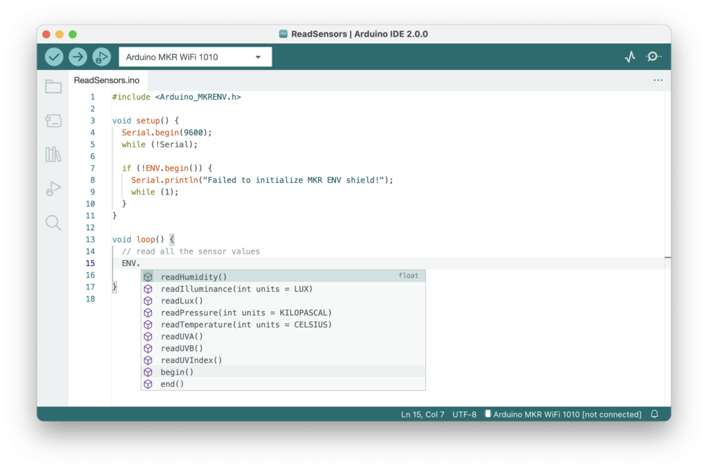
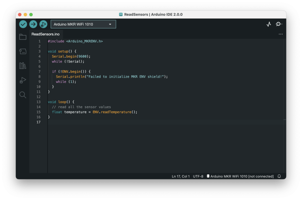
Autocomplete during sketch editing
While typing, the editor can suggest the autocompletion of variables and functions according to your code and the libraries you included:
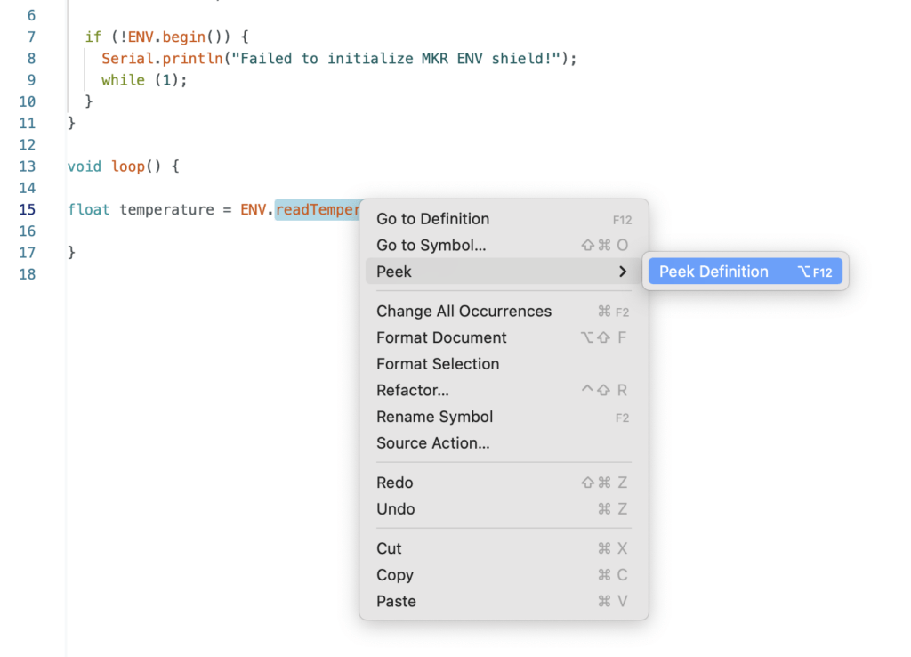
When right-clicking on a variable or a function, a contextual menu will provide navigation shortcuts to jump to the line (and file) where they are declared:
Dark Mode
If your eyes are feeling the strain you can quickly change settings and switch to Dark Mode. Some of you may have used this during the Beta, but our design team has reworked the entire Dark Theme to make it more consistent, beautiful and easy on the eye.
Never lose a sketch keeping them safely at Arduino Cloud
For people who work on multiple computers or want to store their Sketches securely in the Cloud, the Remote Sketchbook integration is a really useful feature.
Easily switch from one computer to another and keep working. If you don’t have Arduino IDE 2.0 installed on all your machines, just open the Arduino Web Editor and you can code from your browser in the online IDE with access to all your sketches and libraries. There’s no need to worry about losing your sketches either, with Remote Sketchbook you only need one click and they will be pushed securely to the Arduino Cloud.
Work offline and sync later, simply bring your sketch down from the Cloud, edit offline and when you are back online click on “Push” and all your changes will be uploaded, meaning all your sketches will always be up-to-date and ready to use.
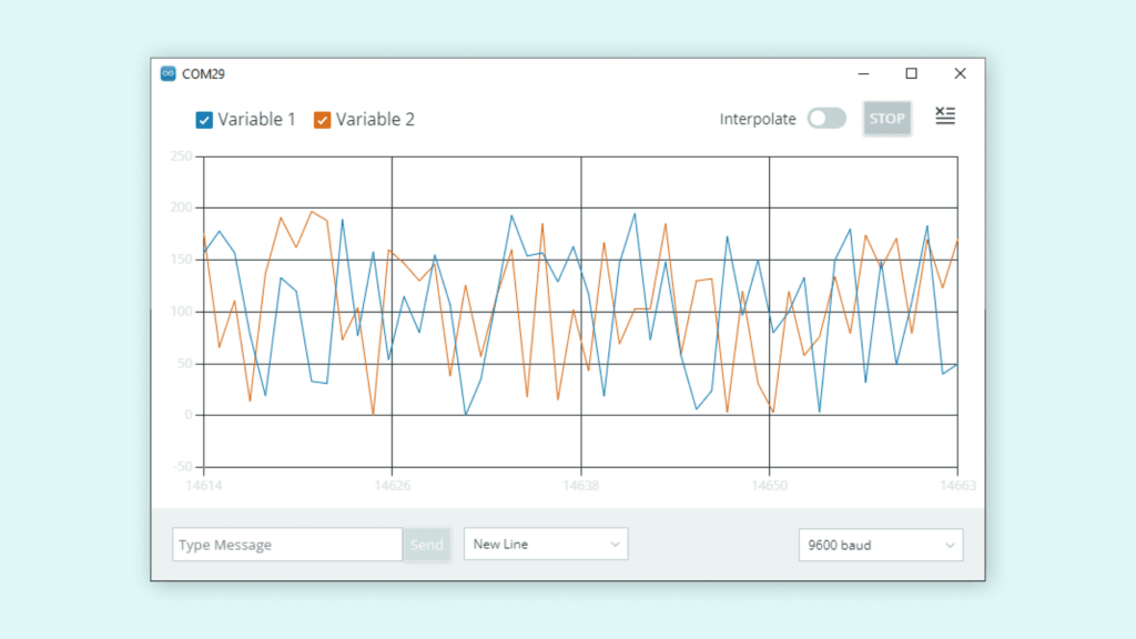
Serial Plotter
The IDE 2.0 features a richer Serial Plotter that is a versatile tool for tracking different data and variables which are received from your Arduino board. The Serial Plotter is a really useful visual tool that will help you to understand and compare your data points better. It can be used for testing and calibrating sensors, comparing values and other similar scenarios.
In-app updates
Our users have always been accustomed to receiving notifications when new boards’ support or libraries updates were available, and IDE 2.0 is no exception. As a plus, the IDE can now itself be updated when a new version is available, so no need to head to the downloads page anymore: click the button and get the latest and greatest.
The new IDE is based on the Eclipse Theia framework, which is an open source project based on the same architecture as VS Code (language server protocol, extensions, debugger). The front-end is written in TypeScript, while most of the backend is written in Golang.
Click here to download the new IDE for your system now. Time certainly flies along, it feels like yesterday when we switched from the old Arduino IDE to version 1.0. Kudos to everyone at the Arduino team and all the beta testers for the works and effort.
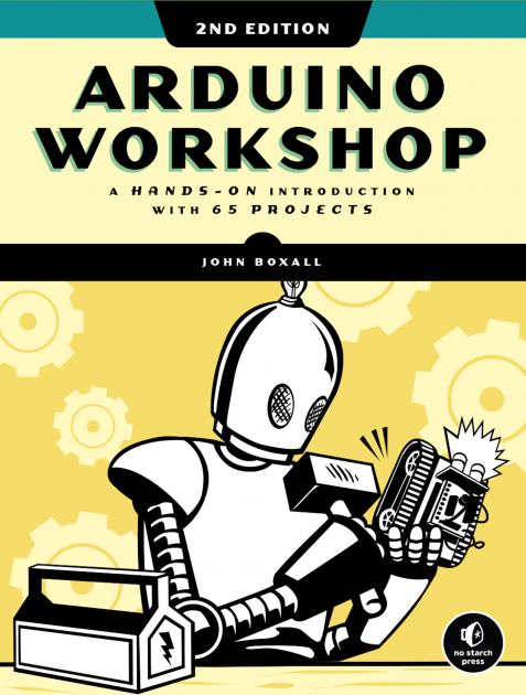
If you’re interested in Arduino and want to get started – please purchase a copy of Arduino Workshop, 2nd Edition – a hands-on introduction to electronics and Arduino with 65 projects. It’s written for the complete beginner – you won’t need any other book or website, and by the end you’ll have the knowledge and skills to turn a wide range of ideas into life.
This is a rewrite of a project I created in 2010 which brought me a lot of joy, so I hope you enjoy it too.Please read the entire article before starting your own. You can still make it today, the parts are easily available.
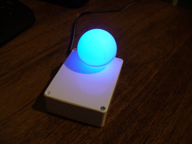
I’ve always enjoyed making Arduino-powered clocks, however over time they tended to become increasingly complex. So to counter this, allow me to introduce you to “Blinky” the one-eyed clock:
It reminds me of the giant killer orb “Rover” from “The Prisoner“… Using a minimal Arduino bootrom system, a DS1307 real time clock IC and an RGB diffused LED, you can make a clock that blinks the time, using the colours of the LED to note different numerical values.
For example, if the time is 12:45, the clock will blink red 12 times, then show blue for a second (think of this as the colon on a digital clock) then blink four times in green (for forty minutes), then blink three times in red for the individual minutes.
If there is a zero, blink blue quickly. Then the clock will not display anything for around forty seconds, then repeat the process. Here he (she, it?) is blinking the time:
Setting the clock is simple. It is set to start at 12:00 upon power up. So for the first use you have to wait until about five seconds before midday or midnight, then power it up. To save cost it doesn’t use a backup lithium battery on the real-time clock IC, but you could add one if required. So let’s get started.
The first thing to do was test the RGB LED for brightness levels, so I just connected it to the digital output pins of my Arduino-compatible board via suitable current-limiting resistors. Red, green and blue to D9, D10 and D11 respectively. Each LED is going to be different, so to ensure maximum brightness without causing any damage you need to calculate the appropriate resistor values.
This is quite easy, the formula is: resistor (ohms) = voltage drop / LED current So if you have a 5V supply, and LED that needs only 2 volts, and draws 20 milliamps (0.2 amps) , the calculation will be: resistor = (5-2)/0.02 = 150 ohms. To be safe I used 180 ohm resistors. The LED was tested with this simple sketch:
This file contains bidirectional Unicode text that may be interpreted or compiled differently than what appears below. To review, open the file in an editor that reveals hidden Unicode characters.
Learn more about bidirectional Unicode characters
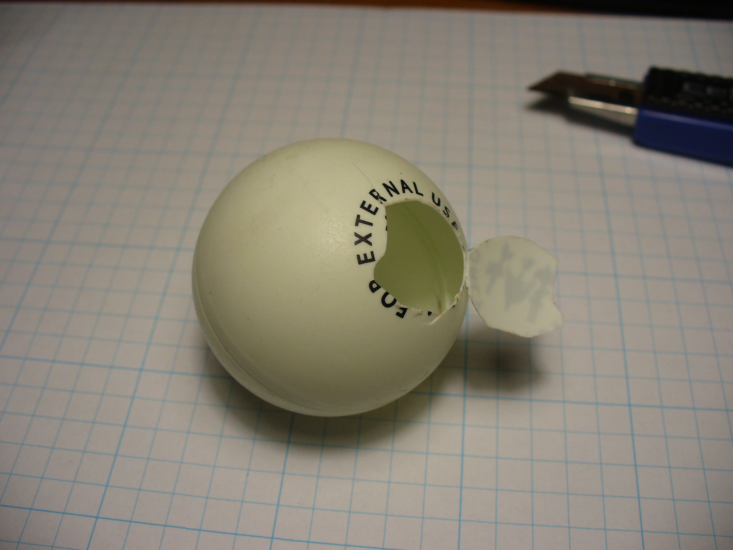
It was interesting to alter the value of d, the delay variable, to get an idea for an appropriate blinking speed. Originally the plan was to have the LED in a photo frame, but it was decided to mount a ping-pong ball over the LED for a retro-style look. Here is a short video of the result of the test:
If you are going to use a ping-pong ball, please be careful when cutting into it with a knife, initially it may require a lot of force, but once the knife cuts through it does so very quickly.
Now it was time to develop the sketch to convert time into blinks. The sketch itself is quite simple. Read the hours and minutes from the DS1307 timer IC; convert the hours to 12 hour time; then blink an LED for the number of hours, display another colour for the colon; divide the minutes by ten and blink that in another colour; then the modulus of minutes and ten to find the individual minutes, and blink those out. Here is the first test sketch:
This file contains bidirectional Unicode text that may be interpreted or compiled differently than what appears below. To review, open the file in an editor that reveals hidden Unicode characters.
Learn more about bidirectional Unicode characters
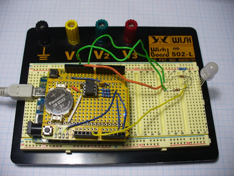
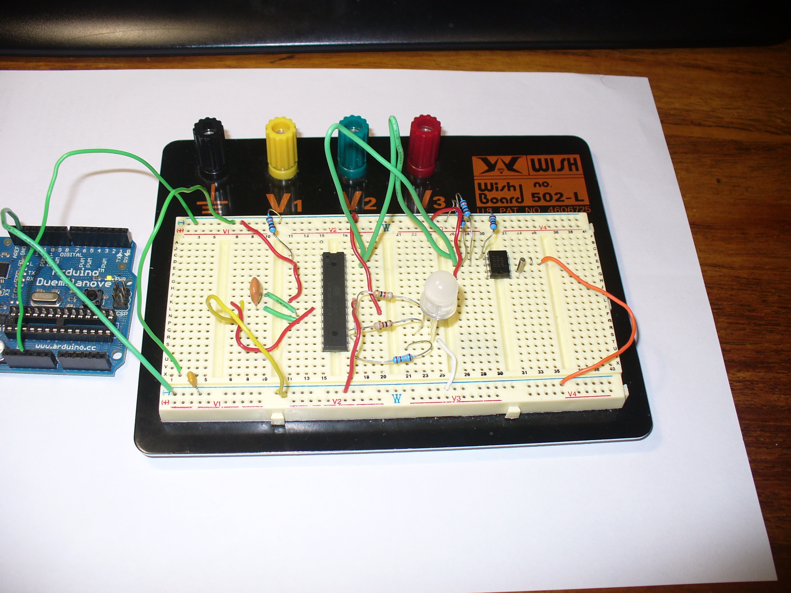
Finally, the code was tested using the Arduino-compatible board and my home-made DS1307 real time clock shield (hey it was 2010, DS32xx were expensive). It is best to use existing hardware while testing, before committing to purchasing new hardware and so on. So here it is on the breadboard:
Here is the prototype in action:
If you’re wondering why the videos are potato-cam quality, smartphones couldn’t record using 4K Ultra HD in 2010.
But perhaps the first version was a little bland. By using analogWrite() we can control the brightness of the LED segments. So I’ve added two more functions, whiteGlow() and blueGlow(); whose purpose is to make the display “glow” by increasing then decreasing the brightness.
And I’ve scaled back the amount of blinking, to make blinky less obvious. So now the display will glow white to announce the forthcoming display of time, wait a second, blink the time (with a blue glowing colon) then stay dark for ten seconds before repeating the process. Here is a quick demonstration of this display style:
Here is the sketch for the above demonstration, and the final one I will use with the hardware prototype:
This file contains bidirectional Unicode text that may be interpreted or compiled differently than what appears below. To review, open the file in an editor that reveals hidden Unicode characters.
Learn more about bidirectional Unicode characters
Once happy with the sketch, I put a fresh ATmega328P-PU with Arduino bootloader in the board and programmed it with the sketch, to be used in the final version. The next step is to build my own hardware. The last hardware unknown is the amount of current the circuit draws. Once I know this the correct voltage regulator and power supply can be decided upon.
I had a fair idea it would be less than 100 milliamps, so I put a 6V battery onto supply duty via a 78L05 5V regulator (data sheet), and recorded the result:
So it varies, between 20.5 and 46 mA. As it only reaches 46 mA for a short time, we could consider the constant draw to be averaged out at 30 mA. I really want this to be able to run from a battery, but without having an external lead-acid battery lurking around, it will need a plug-pack with an output voltage greater than 7V DC.
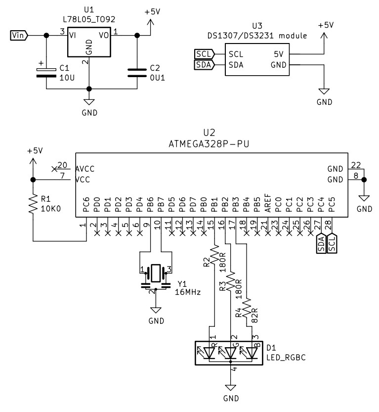
Another alternative would be to run it from a USB socket, a nice source of 5V. If doing so, there wouldn’t be a need for the 78L05 regulator. Which brings us to the circuit diagram, which includes the power regulator. I’ve also altered the resistors to suit the RGB LED used, your values may be different:
And since it’s 2022, not 2010 – I’ve replaced the DS1307 circuit with a RTC module. Y1 is a three pin 16MHz ceramic resonator, we used those in 2010 as they were cheaper and easier than a crystal and two 22pF capacitors.
The circuit does not allow for uploading code, so you will need to program the microcontroller on another Arduino or compatible board, then transfer it to the blinky circuit board as described above. At this stage you should test it again – but using a solderless breadboard. In doing so you can make final hardware checks, and generally make sure everything works as it should. This is also a good stage to double-check you are happy with the display behaviour, default time and so on.
Used the Duemilanove as a lazy 5V for testing.
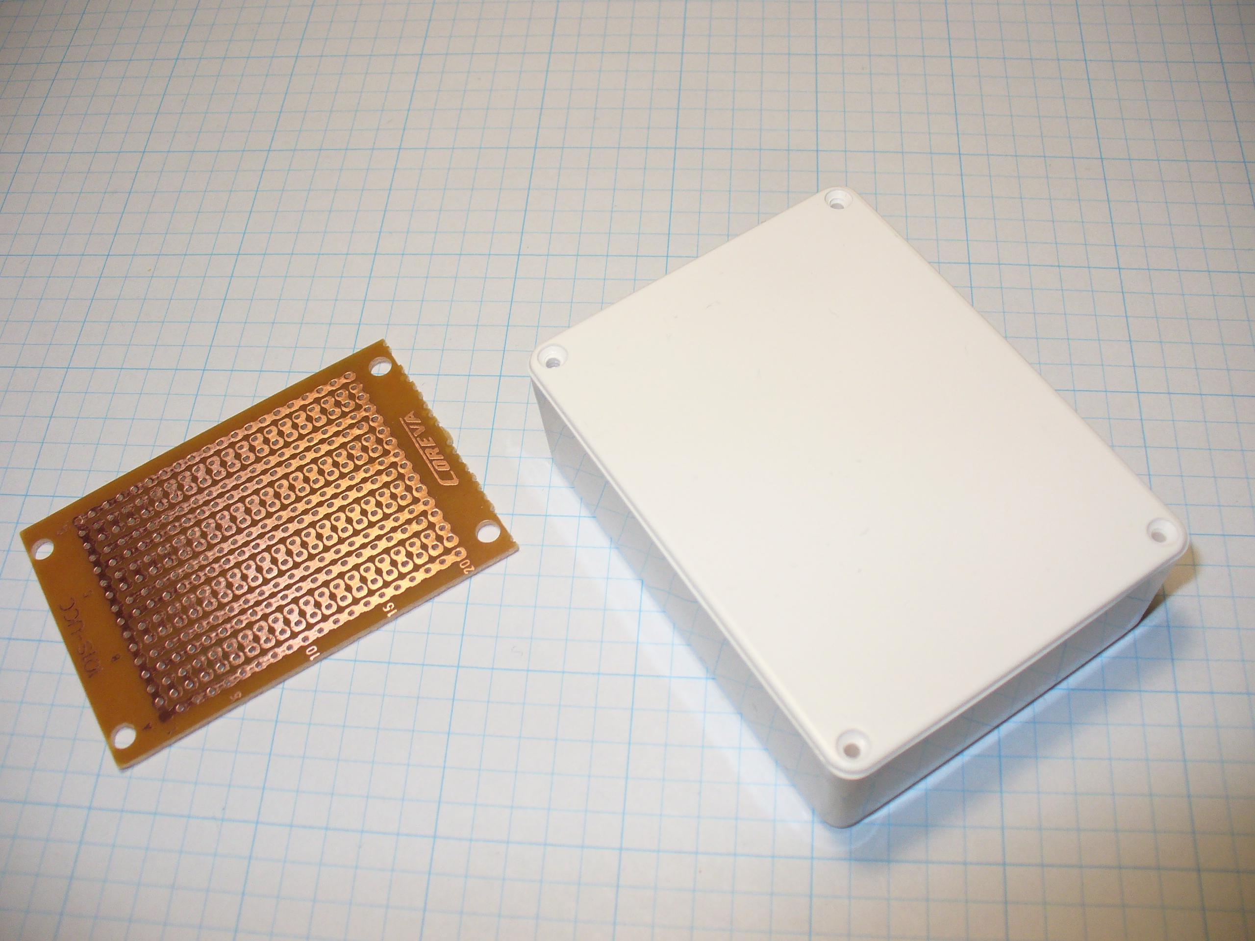
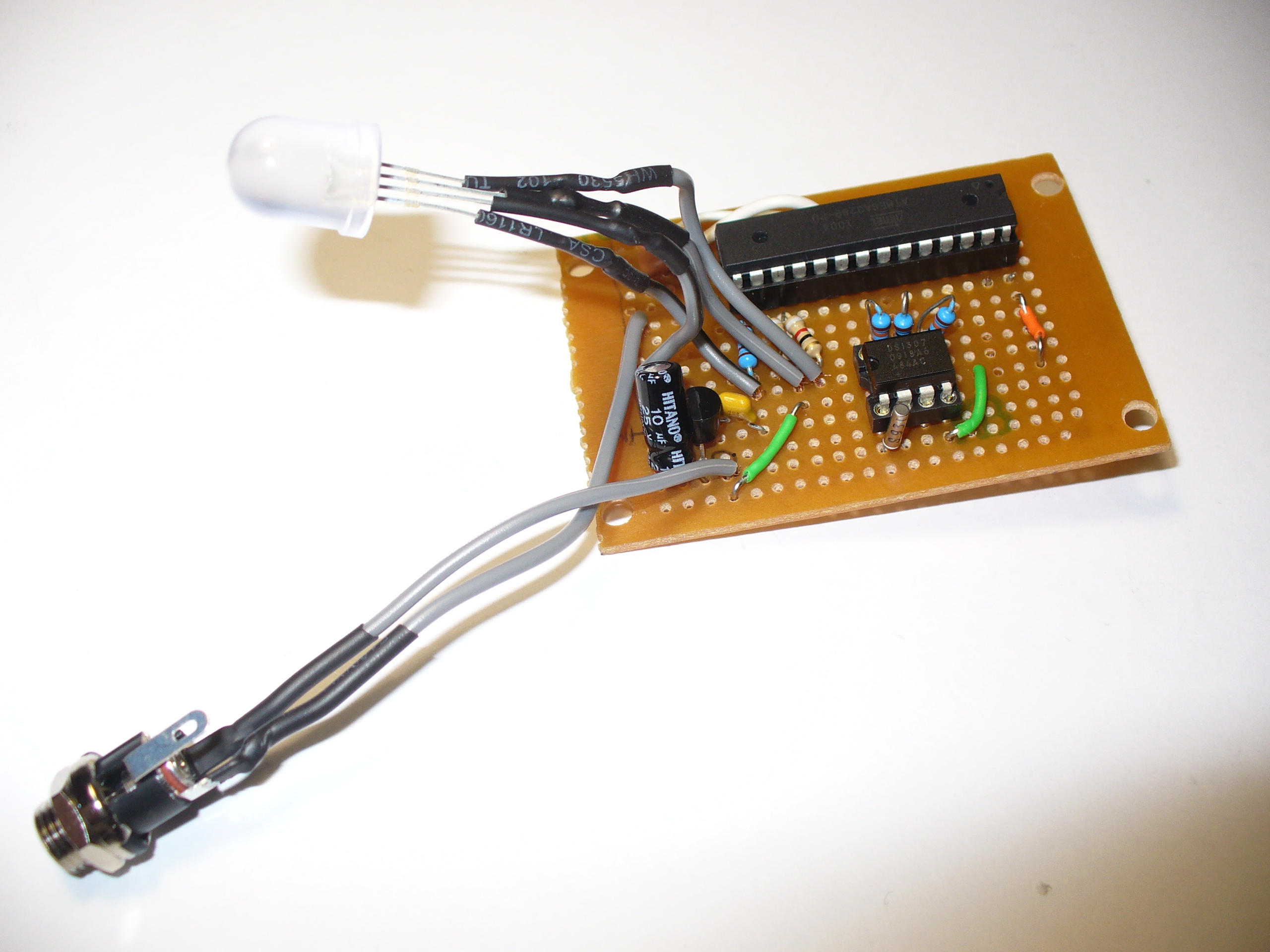
Time to solder up the circuit on some stripboard. Blank stripboard varies, but luckily I found this and a nice box to hold it in:
Stripboard does vary between retailers and so on, so you will need to work out the layout with your own board. In doing so, please double-check your work – follow the layout against the schematic and so on.
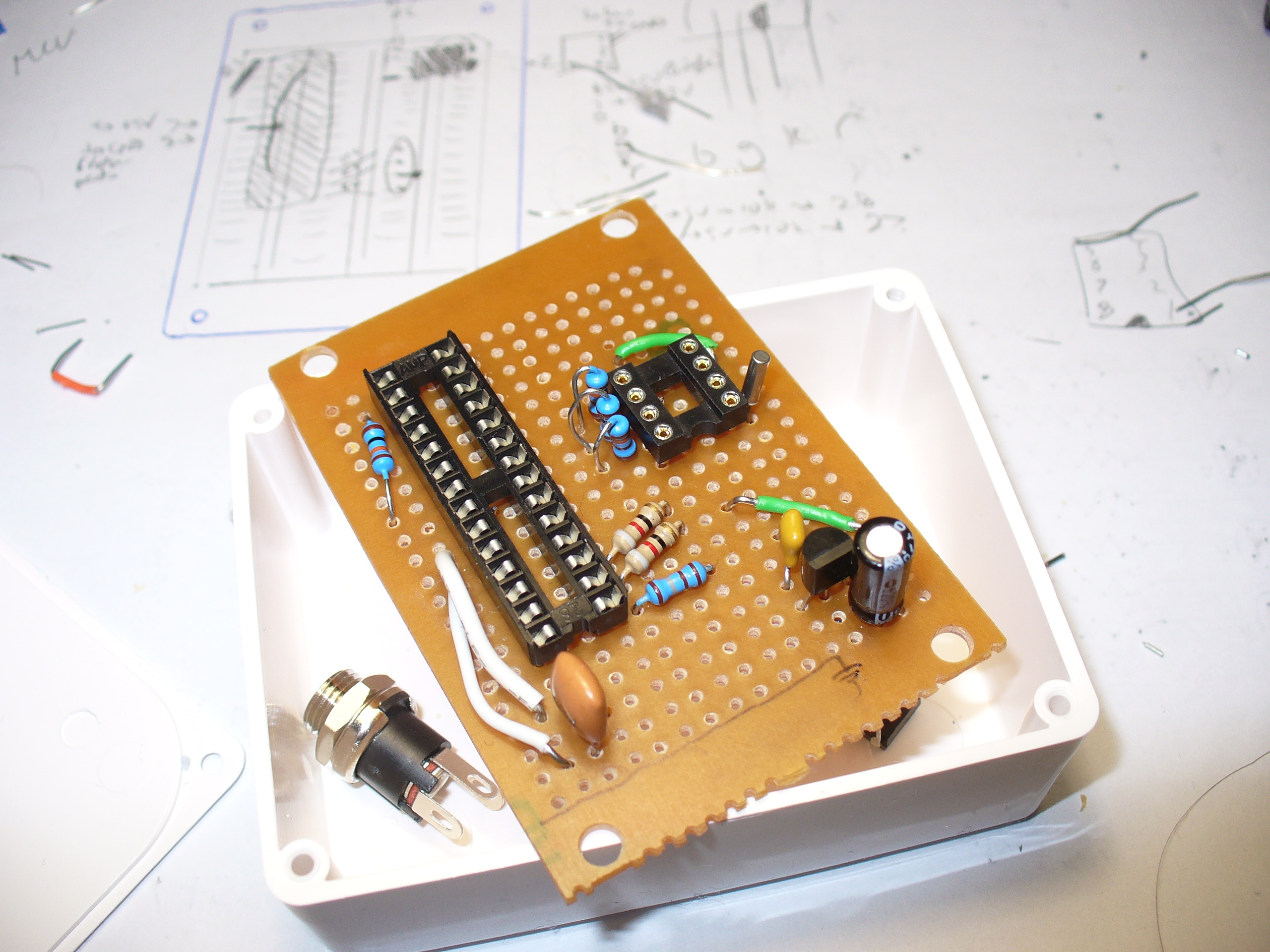
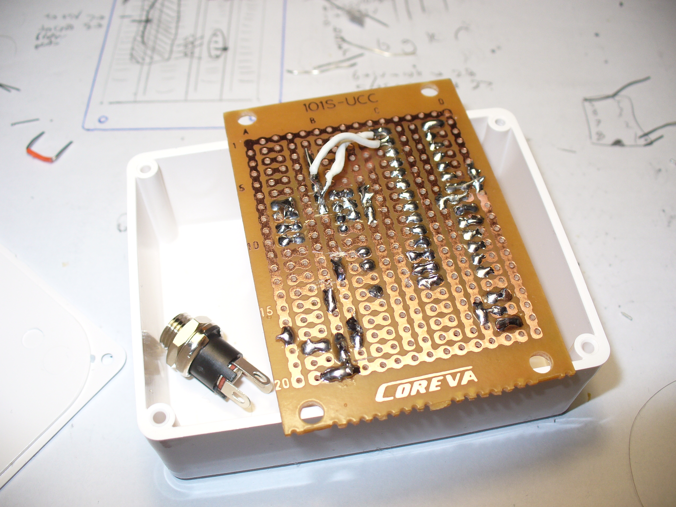
Have a break, then check it again. There is nothing worse than soldering away to realise you are one strip too far over or something. My hand-eye coordination is not the best, therefore my soldering isn’t pretty, but it works:
Note that the images above are using the 2010 circuit – which had a DS1307 sub-circuit.
One would say that there is a good argument for making your own PCBs… and I would agree with that. In 2010 it wasn’t that easy or inexpensive. Now you have KiCAD and Chinese PCB fabs tripping over themselves to give you cheap boards.
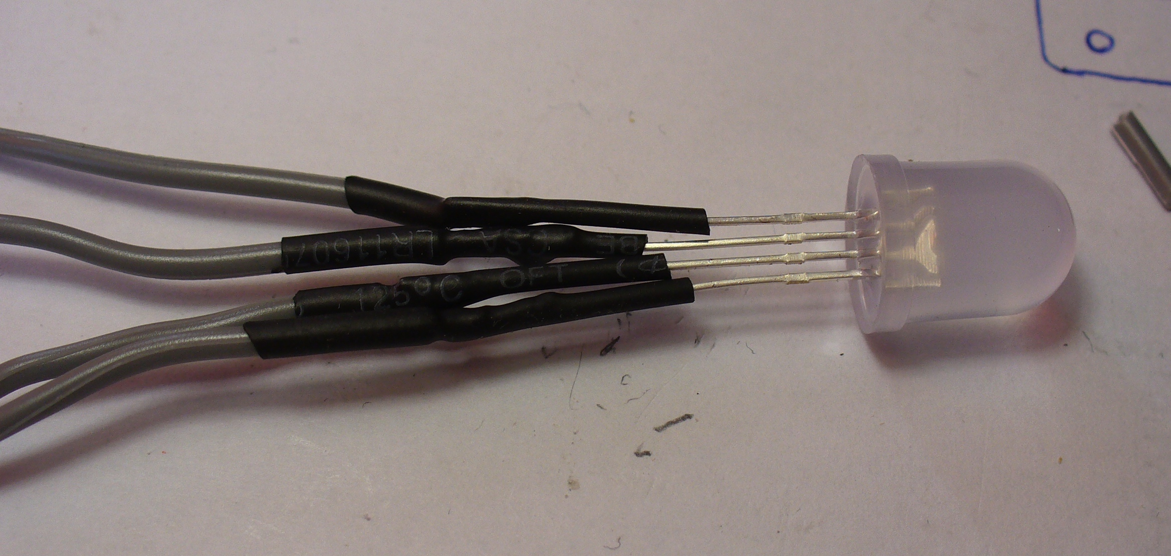
The LED is soldered to some short leads to give it a bit of play, and some heatshrink over the legs to keep them isolated:
And finally, to add a DC socket to feed blinky some power:
The last thing was to check the soldering once more under natural light, to check for bridges or shorts, then have a cup of tea. Upon my return I drilled out a hole in the enclosure lid for the LED, and one one the side for the DC socket, and fitted the lot together… and success! It worked.
I hope you enjoyed making this or at least reading about it. If you find this sort of thing interesting, please consider ordering one or both of my books from No Starch Press, or other book sellers:


You must be logged in to post a comment.